Diagrams
Art is a textual language but there is also a graphical notation for many parts of the language. You can therefore visualize (and in many cases also edit) some of the Art elements using graphical diagrams. The following diagrams can be used:
- State Diagram Shows the state machine of a capsule or class. A single diagram can show all states, pseudo states and transitions also for hierarchical state machines.
- Structure Diagram Shows the composite structure of a capsule. A single diagram can show all parts, ports and connectors also for hierarchical composite structures.
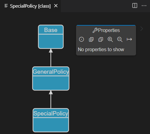
- Class Diagram Shows how capsules, classes and protocols are related by means of inheritance and composition relationships. Also shows ports and parts of capsules and events of protocols.
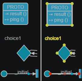
The picture below shows an example of what these diagrams may look like:
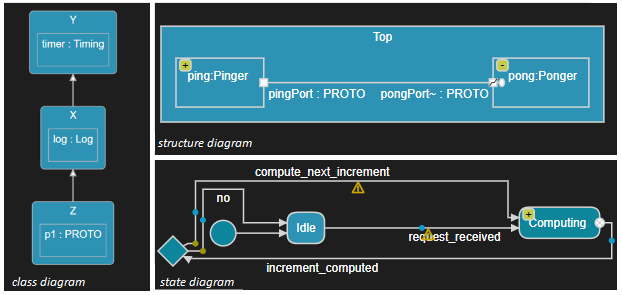
In addition it's also possible to open class diagrams to visualize C++ code.
Opening Diagrams
To open a diagram from an Art file place the cursor inside an Art element. Bring up the context menu and invoke a command for opening a diagram for the Art element: Open State Diagram, Open Structure Diagram or Open Class Diagram. Note that all these three commands are always available, but if the selected Art element cannot be shown in the selected kind of diagram, you will get an error and no diagram will open.
If the cursor is placed on an Art element that has a graphic representation in the form of a symbol or line in the diagram, for example a state in a state diagram, the symbol or line will be highlighted in the opened diagram by selecting it. You can use this feature as a way to navigate from an element in an Art file to the corresponding symbol or line in a diagram. If the diagram is already open, it will be made visible and the selection will be updated.
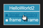
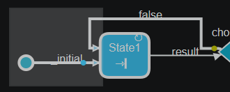
You can also open diagrams from the context menu of an Art file in the Explorer view. In this case the Art file will be searched for an element that can be shown in the selected kind of diagram. If more than one such Art element is found, you will be prompted to pick the one to show in the diagram. For example:
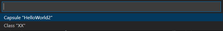
The same prompting happens if you open a diagram from an Art file when the cursor position doesn't indicate which Art element to open the diagram for. All valid Art elements in the file will be listed and you can choose which one to open the diagram for.
You can open multiple diagrams of the same kind in one go by selecting multiple Art files in the Explorer view, and then invoke a command for opening diagrams from the context menu. However, in this case only diagrams for the first element found in each file will be opened (i.e. in this case you will not be prompted in case a file contains multiple elements for which the selected kind of diagram could be opened).
Related Diagrams
If you already have a diagram open, you can open another diagram that is related to that diagram. And if a symbol or line is selected on the diagram, diagrams related to the selected symbol or line can be opened. Press Ctrl+Space to open the diagram's pop-up menu. If the diagram, or the selected symbol or line, has any related diagrams you may see the following commands:
- Open State Diagram
- From a structure diagram that shows a capsule's composite structure, the state diagram of the capsule will be opened. If a part symbol is selected, the state diagram of the capsule that types the part will be opened.
- From a class diagram that shows relationships for a class or capsule, the state diagram of the class or capsule will be opened. If another class or capsule is selected on the diagram, the state diagram of that selected class or capsule will be opened.
- Open Structure Diagram
- From a structure diagram where a part symbol is selected, the structure diagram of the capsule that types the part will be opened.
- From a state diagram of a capsule, the structure diagram of the capsule will be opened.
- From a class diagram that shows relationships for a capsule, the structure diagram of the capsule will be opened. If another capsule is selected on the diagram, the structure diagram of that selected capsule will be opened.
- Open Class Diagram
- From a structure diagram that shows a capsule's composite structure, the class diagram of the capsule will be opened. If a part symbol is selected, the class diagram of the capsule that types the part will be opened.
- From a state diagram of a class or capsule, the class diagram of the class or capsule will be opened.
- From a class diagram where a class, capsule or protocol is selected, the class diagram of that selected class, capsule or protocol will be opened.
For a capsule that inherits from another capsule you can open the state diagram of the inherited base capsule by means of the command Open Inherited State Diagram. If this command is performed on an element that is inherited, redefined or excluded in the state diagram, then the corresponding element in the base capsule will be highlighted. This command is therefore useful for navigating in an inherited state machine.
Automatic vs Manual Layout
By default diagrams are rendered using automatic layout. This means that all symbols are automatically positioned, with default sizes, and lines between symbols are routed in a direct way without bendpoints (in most cases). Text labels of symbols and lines are also automatically positioned. The main benefit with automatic layout is that you don't need to spend time manually creating and maintaining the layout, something that can be rather time consuming, especially for big diagrams. However, automatic layout also has its drawbacks and limitations:
- A good layout of a diagram can help to understand it better. For example, you may want to group elements that are logically related close to each other.
- Small changes in an Art file can lead to rather big graphical changes when automatic layout is used. For example, adding a transition between two states can cause the states themselves to move to a different position to achieve a compact overall diagram layout. While editing an Art file this can give a "jumpy" feeling to diagrams where symbols move around a lot while typing.
- Auto-layouted diagrams may sometimes not be as aesthetically nice as ones that you layout manually.
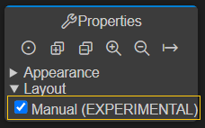
If you want to use manual layout for a diagram, click in the diagram background, expand the Layout section in the Properties view, and mark the Manual checkbox.
Once you have turned on manual layout for a diagram you can start to edit the diagram to get a nice-looking layout:
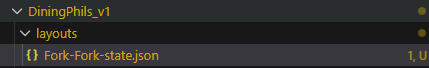
When you save the edited diagram the layout information is stored in a JSON file under a layouts subfolder. This subfolder is placed in the folder where the Art element is located to which the diagram belongs (the so called "context" element of the diagram). There will be one such file for each diagram that uses manual layout. The name of the file is <ArtFile>-<ArtElement>-<DiagramType>.json where <ArtFile> is the name of the Art file and <ArtElement> is the name of the Art element that is the context element of the edited diagram. <DiagramType> is either "state", "structure" or "class".
Sometimes you may want to change the diagram layout by editing the layout JSON file, for example to move a symbol to a specific coordinate. This is possible and the diagram will update when you save the JSON file. But be careful not to change the JSON file in a way that makes it invalid.
Moving Symbols and Text Labels
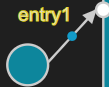
To move a symbol, just select it and drag it to a new position on the diagram. You can also move the text labels of some symbols and lines to avoid that they overlap with other graphical elements on the diagram. For example, assume the label of an entry point overlaps with the incoming transition line:
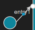
By selecting and moving the label a little up and to the left the overlap can be avoided:
If you move a nested symbol outside the boundaries of its container symbol, the container symbol will be automatically resized to contain the nested symbol also afterwards.
Resizing Symbols
With manual layout it's possible to resize some kinds of symbols. Yellow "resize" handles at symbol corners will appear for a selected symbol that can be resized:
If you increase the size of a nested symbol, the size of its container symbol will also grow if required, so that it still contains the nested symbol afterwards. Note that you cannot make a symbol too small, for example so small that a text label it contains won't fit.
Routing Lines
In a diagram with manual layout you can freely route lines. Red "bendpoint" handles appear when you select a line that can be manually routed:

Move the source and target bendpoint to decide where on the source and target symbol the line should connect. Create a new bendpoint by moving the opaque middle bendpoint that appears between each pair of bendpoints.
To delete all bendpoints, and make the line straight again, select the line and press Ctrl+Space and then perform the command Make Straight. To only delete some of the bendpoints, select them, press Ctrl+Space and then perform the command Delete Bendpoint.
Discarding Layout Information
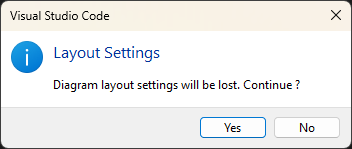
If you want to go back from manual to automatic layout, just uncheck the Manual checkbox. You will be prompted for confirmation, and if you proceed the JSON file with the diagram's layout information will be deleted when you save the diagram. This operation is not undoable!
Alternatively you can delete the layout JSON file from the Explorer view. In this case, the operation is undoable.
If you only want to discard layout information for some of the symbols or labels on a diagram, select them and press Ctrl+Space and then perform the command Discard Manual Layout. Layout information for the selected symbols or labels will then be deleted and they will go back to their default positions and sizes. This operation is undoable.
Maintaining Layout Information
The JSON file that holds layout information for a diagram contains references to Art elements. Consider the example below:
[
{
"context": "::MyCapsule",
"diagramType": "state",
"layouts": [
{
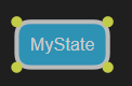
"element": "MyState",
"x": 80.0,
"y": -100.0
}
]
}
]
MyCapsule references a capsule, and MyState references a state in the state machine of that capsule. When you make changes to the Art file, these references are usually updated automatically, to ensure that the layout information remains valid. However, note the following:
- References will be updated when you rename an element, regardless if you rename it by direct typing in the Art file, or if you use the Rename command. However, it's recommended to use the Rename command since there are some situations where rename by direct typing will be unable to update all references.
- If you rename the context element, i.e. the element that owns a diagram (like
MyCapsulein the example above), and that diagram is currently open, then it will be automatically closed and reopened so the new element name is shown in the diagram editor tab. Code RealTime tries to reopen the diagram into the same editor tab group, but sometimes this is not possible and the diagram will then appear elsewhere. - If you rename an Art file (using the Rename context menu command in the Explorer view), layout files for all its diagrams will be updated. If any of those diagrams are currently open they will be automatically closed and reopened.
- If you delete an element, references to it from layout files are not always automatically deleted. There is no harm in keeping layout information for deleted elements, and if the deletion is undone, the preserved layout information ensures that the element retains the same layout as before. However, if you want you can manually remove layout information for deleted elements from the JSON files.
- There are also other editing scenarios that can invalidate layout information for one or several Art elements. Examples include refactorings such as inheritance rearrangements. Also in these cases layout information is retained in the JSON files and can be manually updated or deleted, if required.
Layout Validation
Code RealTime validates layout files and reports found problems as warnings (shown both in the layout file and in the Problems view). This helps you detect layout information that is wrong, for example because of refactoring operations, mistakes made when merging layout files, etc. Warnings in a layout file just means that some or all of the layout settings in the file will be ignored when opening the diagram, and that the affected parts of the diagram will fallback to use automatic layout instead. However, it's recommended to nonetheless fix such warnings to ensure the diagram appears as expected.

Layout warnings are only shown for diagrams while they are open. Pay attention to the layouts folder in the Explorer view. If it appears in orange there is at least one open diagram where one or many layout problems have been detected.
Layout problems reported in a layout file are typically caused by incorrect references to Art elements. But there are also other kinds of layout problems that are detected when a diagram is opened:
- Logical errors in diagram layout values (coordinates, sizes etc) which prevent the editor to apply the layout, and where the default layout will be used instead.
- Graphical ambiguities where the diagram layout does not match the semantics of the Art elements.
These types of layout validation problems are described below.
Logical Layout Errors
The values specified in a layout file for coordinates, sizes etc. may contain logical errors. Examples of such errors are:
- the size of a container symbol is not big enough to contain all its contained symbols
- the location of a symbol, label or line bendpoint is outside the boundaries of the container symbol
When such a logical layout error is detected for a symbol, line or label it will revert to use its default layout. For a label this means a default location near the symbol or line to which it belongs. For a symbol the default layout means a small size, and a position that is determined by the automatic layout algoritm. And for a line a default layout means a straight line without any bendpoints.
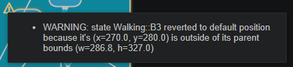
To help you detect when a logical layout error makes a symbol, label or line revert to its default layout, the editor shows a warning for it. It's not possible to directly navigate to the place in the layout file where the faulty layout is specified, but the tooltip of the warning shows the fully qualified name of the element so you can search and find its layout in the layout file.
Here is an example of a warning caused by a logical layout error:
Graphical Ambiguities
With manual layout it's possible that a symbol in a state diagram shows up inside the symbol of a composite state, even if the corresponding Art element is not nested within that state. The diagram editor will detect such graphical ambiguities and show a warning to avoid that the diagram is misinterpreted. The warning is placed both on the composite state symbol and the symbol that appears inside it. Here is an example:
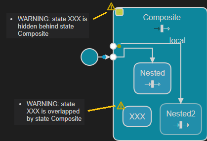
Here Nested and Nested2 are substates of Composite while XXX just happens to appear inside it (either because it was moved or that Composite was resized).
Note that if the element of the ambiguous symbol comes before the state in the Art file, the ambiguous symbol will not be visible since it then will be hidden behind the state symbol. In this case only the warning on the state symbol can be seen.
If you observe warnings about graphical ambiguities you should update the manual layout of the diagram to get rid of them.
Navigating from Diagram to Art File
If you double-click a symbol or a line in a diagram, the Art element that corresponds to that symbol or line will be highlighted in the Art file. Note that you need to double-click on the symbol or line itself, and not on a text label shown in the symbol or on the line. However, as an alternative you can instead hold down the Ctrl key and then click on the text label. It will then become a hyperlink that navigates to the Art element that corresponds to that text label. You need to use this approach in case a symbol has multiple text labels each of which represent different Art elements. For example:
In state diagrams you can also double-click on icons that are shown for transitions that contain effect and/or guard code. The presence of effect code is indicated by a blue icon, and guard code with a yellow icon.
![]()
Double-clicking these icons will highlight the code snippets in the Art file.
Working with Diagrams
Zooming and Panning
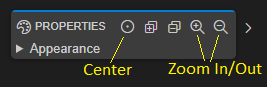
When a diagram is opened it is initially centered and with medium zoom level which makes all text labels big enough for reading. However, if the diagram is big then all contents may not be visible unless you zoom out. You can zoom the diagram using either the mouse scroll wheel or by means of the two-finger zoom gesture on a touch pad. You can also zoom using the buttons in the Properties view toolbar. There you will also find a Center button which will restore the diagram to its original zoom level.
Alternatively you can use the command Fit to Screen which will set the zoom level so that the entire diagram fits the size of the diagram editor. Note that this command must be invoked from the general Command Palette or by means of the keyboard shortcut Ctrl+Shift+F.
It's also possible to work with a big diagram without zooming, but instead panning the viewport so that a different part of the diagram becomes visible. To pan the viewport click anywhere in the diagram background and drag while holding down the mouse button. Note that there are no limits to panning which means you can move the viewport as far away from the center of the diagram as you like. Use the Center or Fit to Screen command for panning back the viewport to its original position. Note that if a symbol or line is selected, the Center command will move the viewport so that the selected symbol or line appears in the middle.
When working in a zoomed-in diagram that contains composite symbols (for example a composite state) it can happen that the diagram background is not visible in the viewport. In this case you can instead pan the diagram with any of the below approaches:
- Use the Page Up or Page Down keys.
- Use the Up or Down keys. However, this only pans the diagram if no symbol is selected (otherwise the selected symbol will be moved).
- Press and hold down the Space key (the cursor changes into a hand), and then click and drag anywhere in the diagram.
Selecting Elements
To select a symbol, label or line, click once on it. A selected symbol gets a thick outline and, if it is resizable, also yellow resize handles. A selected label is drawn in yellow and, if it belongs to a symbol, resize handles also appear on that symbol. A selected line gets a thick outline and red bendpoint handles.
To select multiple elements hold down the Ctrl key while clicking on symbols, labels or lines. As an alternative you can hold down both Ctrl and Shift (on Mac Cmd and Shift) to get a "crosshair" cursor, and then make a "marquee selection" by drawing a rectangle.
All symbols and lines (but not labels) that the marquee rectangle touches will become selected. Note that you cannot make a marquee selection if another element is already selected, so click in the diagram background to reset the selection first.
Collapsing and Expanding Symbols
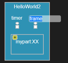
State and structure diagrams can be hierarchical. A state diagram is hierarchical if it contains a composite state with a nested state machine. A structure diagram is hierarchical if it contains a part typed by another capsule with nested parts or ports. By default symbols that contain nested symbols are collapsed to minimize the size of the diagram:

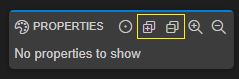
To expand a collapsed symbol click the yellow button. The symbol will then be resized to show the nested symbols. Click the button again to collapse the symbol and hide the nested symbols. You can use the Expand All and Collapse All buttons in the Properties view toolbar to expand or collapse all symbols so that the full hierarchical diagram becomes visible or hidden.
Information about which symbols that are currently expanded will be remembered if you save the diagram. This information is stored in the file .vscode/art_diagram_settings.json.
Invoking Diagram Commands from Keyboard
Many diagram commands mentioned above can be invoked using the keyboard. Press Ctrl+Space in a diagram to open a pop-up menu from where you can invoke a diagram command.
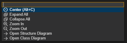
In this pop-up menu you also find convenient commands for navigating to related diagrams. For example, from the state diagram of a capsule you can navigate to the structure and class diagrams of that same capsule.
Diagram Appearance
Certain properties on Art elements control how they will appear in a diagram. Currently it's possible to configure which color to use for most elements in diagrams. See the color property for more information.
Diagram Filters
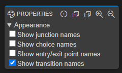
To avoid cluttered diagrams with too many text labels, certain information is by default hidden. If you click in the background of the diagram, the Properties view will show various Appearance filters that you can turn on or off for showing or hiding such additional information. Here is an example of the filters available for a state diagram:
Information about applied filters will be remembered if you save the diagram. This information is stored in the file .vscode/art_diagram_settings.json.
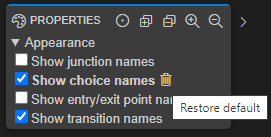
Diagram filter properties that have been modified are shown in boldface, and a "Restore default" button appears for them. You can click this button to restore the filter property to its default value.
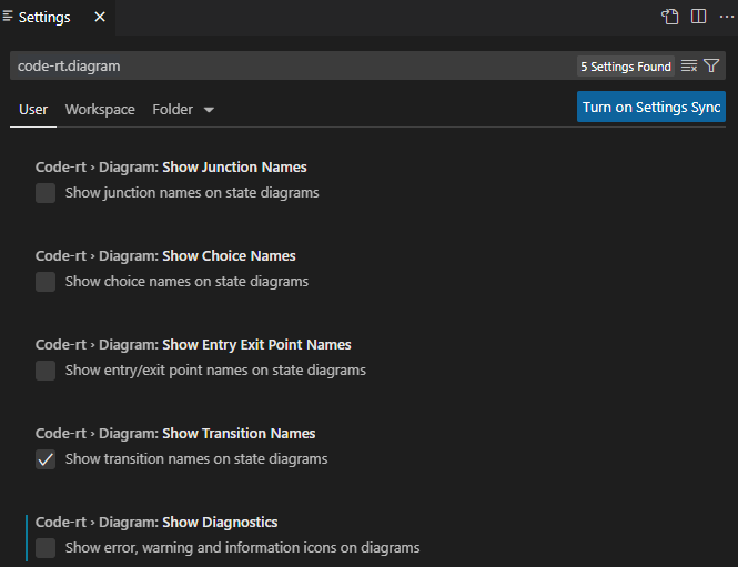
You can also set diagram filters globally using diagram settings. Such filters will apply to all diagrams unless a more specific filter has been set on an individual diagram. You can find these settings by filtering on code-rt.diagram in the Settings editor:
Note that some diagram filters can only be set globally, and not for individual diagrams.
Elements in the Properties View
The Properties view can show additional Art elements when you select a symbol or a line. For example, it shows internal transitions of a state.
![]()
Showing such elements in the diagram itself would risk making it cluttered, especially when there is a large number of elements.
You can double-click the Art elements in the Properties view to highlight them in the Art file. For internal transitions the same blue and yellow dots are shown as for regular transitions in diagrams. Double-click the blue dot to navigate to the transition effect code and the yellow dot for navigating to the transition guard code.
Moving the Selection Upwards
The Properties view has a button in its header for moving the selection upwards in a diagram. This button lets you select the enclosing symbol in case a nested symbol or line is selected.
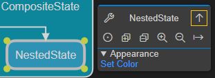
One scenario when this button is useful is when a nested state is selected, and you want to know which internal transitions that may be triggered when that state is active. The Properties view shows the internal transitions defined for the currently selected state (see above), but in addition to those, internal transitions defined on enclosing states can also trigger when the state is active. Use the button in the Properties view header for moving the selection upwards in the hierarchical state machine to see all internal transitions that can trigger.
If the button is pressed when a top-level symbol or line is selected, then the diagram itself is selected. The same thing happens always if you hold down the Shift key when pressing the button. This has the same effect as clicking in the diagram background. It can be useful when you need to see the diagram properties, but the diagram background is not visible (e.g. because the diagram is big and zoomed-in). For example, if you want to turn on a diagram filter you can Shift-click the button, turn on the filter, and then continue to work, without first having to zoom out the diagram so you can click in the diagram background.
Renaming Elements
You can rename an Art element shown in a diagram by selecting the symbol or line to which the text label belongs and then press F2.
Note that this is a "rename refactoring" and all references to the renamed element will be updated too.
Creating and Editing Elements
Note
Creating and editing elements is supported in state and structure diagrams but not in class diagrams.
To create a new element in a diagram use one of the New ... commands in the pop-up menu that appears when you press Ctrl+Space. These commands are the same as appear when you use Content Assist in the Art text editor. Which commands that are available depends on what is currently selected in the diagram. If an element is selected in the diagram, a new element will be created inside that element. Otherwise the new element will be created as a top-level element (possible in state diagrams but not in structure diagrams).
To edit an existing element, select it in the diagram and use the Properties view for editing it. There are certain properties that are common for many elements, such as the color property, but most properties are specific for the element that is selected.
Elements are created and edited by updating the Art file, which in turn will update the diagram. Just like when you use Content Assist in the Art text editor a created element will initially get default values for its properties, for example the name. The default value becomes selected so you can directly type to replace it with something else.
You can of course undo a change by pressing Ctrl+z (Undo) in the Art text editor.
State Diagram Editing
In a state diagram where nothing is selected, the New ... commands will create new top-level elements directly in the state machine.
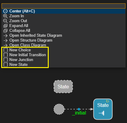
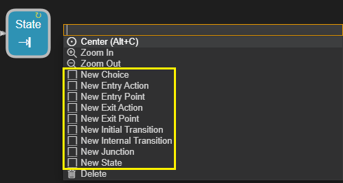
If a state is selected you can create the following elements inside it (turning the state into a composite state, if it was not already composite).
To create a transition in a state diagram you first need to select the source state (or pseudo-state) and then the target state (or pseudo-state). Then press Ctrl+Space and perform either New Triggered Transition or New Non-Triggered Transition (depending on if the transition needs any triggers or not).
![]()
You can redirect a transition, i.e. to change either its source (state or pseudo-state) or its target (state or pseudo-state). You can do it from a state diagram by selecting both the transition and the new source or target. Then press Ctrl+Space and perform either Set Transition Source or Set Transition Target. This will redirect the transition by changing its source or target. If you want to change both the source and target just repeat the procedure once more.
For example, in the diagram below we have selected the transition between states Ready and Heating and also the CoolOffState. We then select Set Transition Source in the menu. This will redirect the transition to instead go from state CoolOffState to state Heating.
![]()
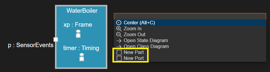
Structure Diagram Editing
In a structure diagram it's not possible to create anything unless something is selected in the diagram. This is because a structure diagram always has a single capsule as its top-level element. If the capsule is selected you can create parts and ports in it.
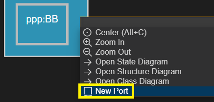
If a part is selected you can create a port in the capsule that types the part. In the example below a port will be created in capsule BB.
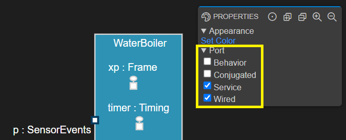
Both parts and ports have several properties that can be edited using the Properties view.
Deleting Elements
Note
Deleting elements is supported in state and structure diagrams but not in class diagrams.
You can delete an Art element shown in a diagram by selecting the symbol or line that represents the element and then press the Delete key. Alternatively use the command Delete in the Ctrl+Space pop-up menu. Multiple symbols or lines can be selected in order to delete many Art elements in one go.
Note that elements are deleted by removing them from the Art file, which in turn will update the diagram. All content within the deleted element will be lost, including any comments. However, you can of course undo the deletion by pressing Ctrl+z (Undo) in the Art text editor.
Exporting Diagrams as SVG
Diagrams can be exported as SVG files. This makes it possible to include diagrams in documents such as reports and presentations. SVG (Scalable Vector Graphics) is a scalable vector format which lets exported diagrams be zoomed and resized without losing image quality. Exporting a diagram as SVG is therefore much better than taking a screenshot of it.
To export a diagram as SVG follow these steps:
- Open the diagram
- Set-up the diagram to display the information you want to include in the exported SVG file. For example, apply diagram filters and collapse or expand symbols.
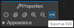
- Click the "Export as SVG" button in the Properties view toolbar. The exported SVG file will be saved in a subfolder
DiagramsAsSVGin the workspace folder.
Alternatively, the command Code RT: Export as SVG (available in the Command Palette) can be used. It will export the diagram that is open in the currently active editor.
You can export all diagrams for an Art element, or even all diagrams for all Art elements defined in a certain Art file, by means of another command Code RT: Export Diagrams as SVG. For the latter scenario you can also do it by means of a context menu command that is available for Art files in the Explorer view:

Class Diagrams for C++ Code
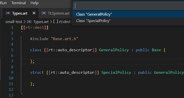
If you have C++ types defined, either in [[rt::decl]] code snippets in Art files, or in C++ header files, you can visualize them in a class diagram. Right-click in the Art or C++ text editor and perform the command Open Class Diagram. If the cursor is placed on a specific type, that type will be shown in the diagram. Otherwise you first need to select which type you want to generate the diagram for.
The class diagram will show the type's relationships to other types, for example its inheritance hierarchy and references or pointers to other types. It will also show member variables and member functions.
Diagrams that visualize C++ code are read-only, but you can collapse or expand types as you explore the diagram. You can double-click elements shown on the diagram to navigate to the corresponding C++ declaration. Note that if you change anything in the C++ code the diagram doesn't update automatically, so you need to close and reopen it to show recent changes.
Note
If the C++ code you want to visualize is located in a code snippet of an Art file, it's required that corresponding generated C++ files are present. The best way to ensure this is to ensure you always have a TC set as active.